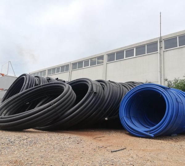
HDPE-100
HDPE-100
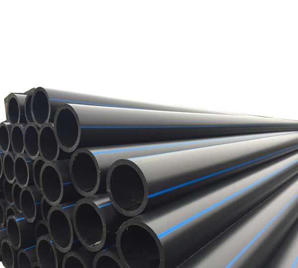
DEKAPIPE Hdpe pipe (High Density Polyethylene Pipe) is a hard, lightweight, robust pipe with a smooth inner and outer surface. Handling requires a minimum of heavy equipment and is easily implemented in all field conditions, from ice to wet, swampy areas.
Hdpe pipes do not support rust, making it indispensable for you. Resistant to salt water and chemicals likely to be found in sanitary sewage wastewater. It provides better resistance to corrosive acids, bases and salts than most pipe materials.
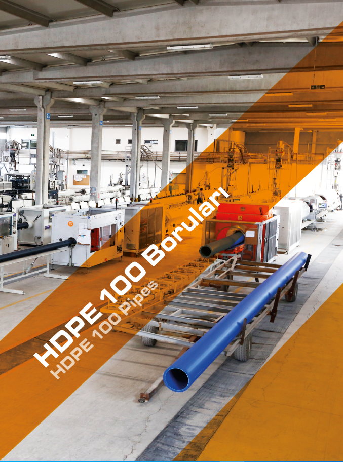
HDPE-100
High Performance
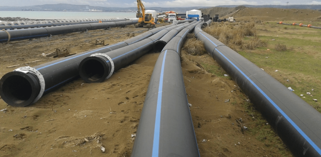
Hdpe Pipes are indispensable for prestigious projects with their high performance and quality. It is used safely in mining, drainage systems, water networks, water transfer, gas collection lines and solid waste storage areas.
Ease of Transport and Loading
HDPE Pipes Provide Ease of Transportation and Loading
Saving
Hdpe Pipes are easier to process, install and save costs during the construction process than hard concrete pipes. Structurally, other pipes are prone to cracks and breakage.
DEKA PIPE’s HDPE 100 pipes are produced with a high quality and stand out. Our PE 100 pipe and fittings had reached the point 3 in the petrochemical technology (HDPE Generation 3), HDPE (High Density Polyethylene)mean Turkish (Yüksek Yoğunluklu Polietilen) and had emerged in 1950, the Environmental Stress value (a) tor this product has given in the tirsi time as 3,2 Mpa and have been developed through the time to reach 6,3-8,0 and 10 Mpa, the value today has become PE 100. The Raw materials of these days have the Environmental Stress Value number 12,5 Mpa , bu t even if you find il the Petrochemical facilities had not started the production with this value yet. This is the meaning of raising the value, The highest the value of the environmental stress the more powerful raw materials structure, and !hat means thinner wall thickness with more resistant pipe and providence of perfect water transmission.
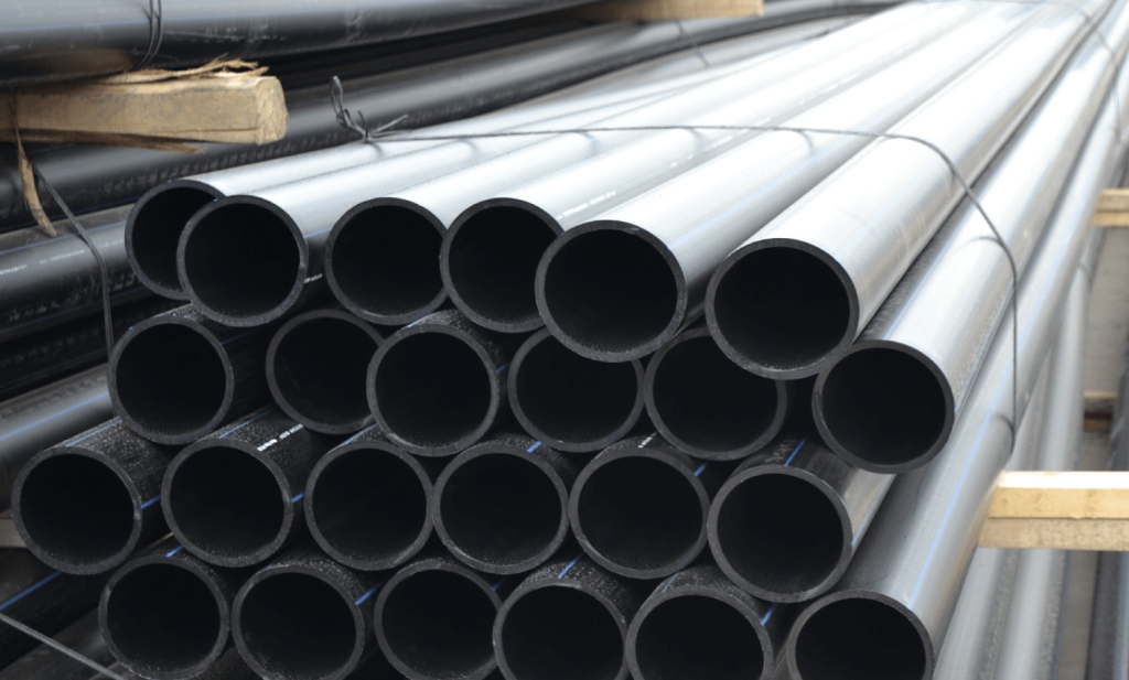
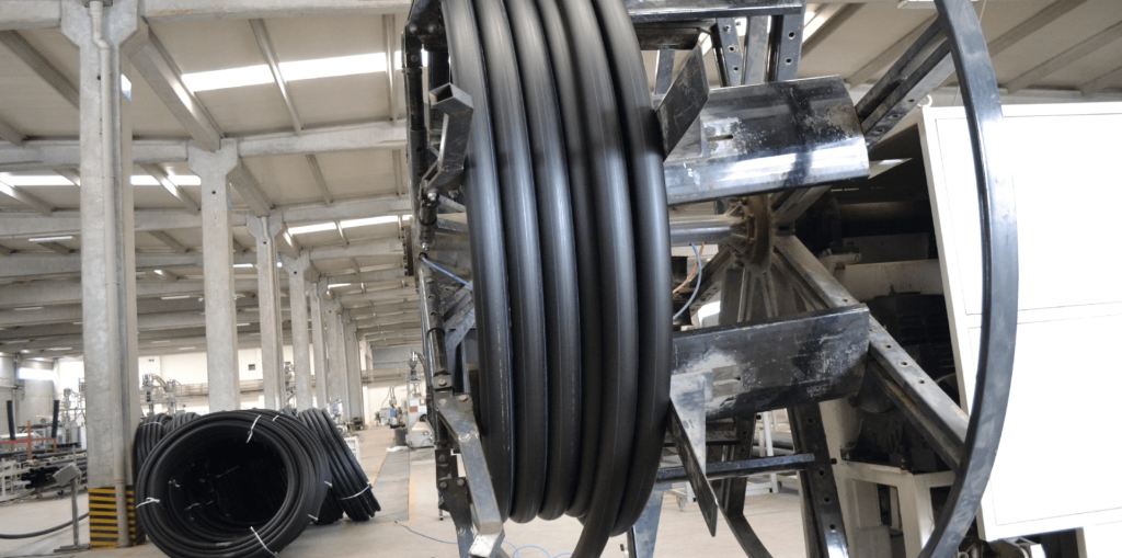
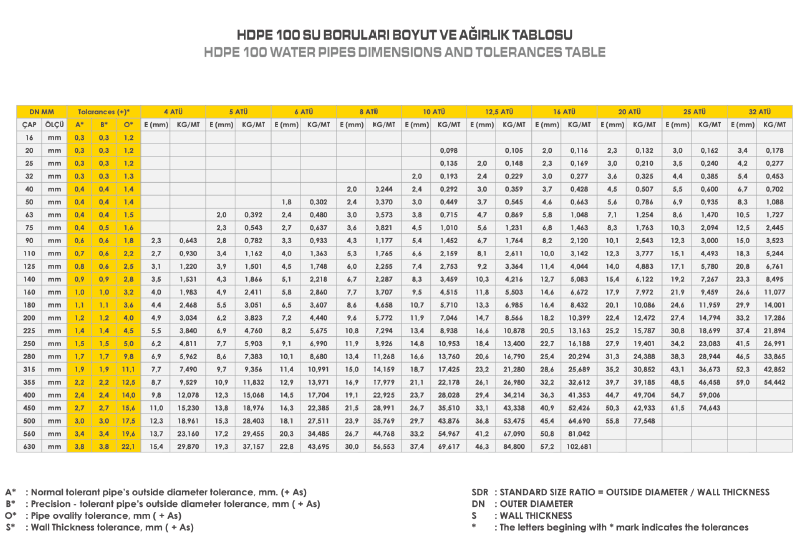
As DEKA PIPE Company we follow !he development of the quality laboratories from a very close view and always searching tor any new. Our products diameters from 20 mm to 630 mm and produced with the highest quality. Thanks to the polyethylene features, is the pressurized clean water system which is one of the besi alternatives, water pressure systems of underground and above ground, Sea Discharge projects, fish- producing farms as they use it to make a production cages. Usually the color of the polythene pipes that used above !he ground is black. DEKA PIPE prefer the PE 100 raw materials in production, this high quality raw material and the produced good from it are being tested individually and shipped to the costumer
GENERAL FEATURES
As a result of petrochemical developments, plastic raw material diversification developments have reached extreme points. The first use of PE raw materials (PE 32 – LDPE) in drinking water pipes dates back to the 1950s. PE 63 raw material was developed and used in low pressure systems, and it could be used in natural gas systems up to 4 bar. After PE 63, PE80 raw material started to be used. It has been used in drinking water and natural gas networks. At the beginning of 1990, PE 100 raw material provided high performance and became an economical solution in drinking, potable water and natural gas networks.
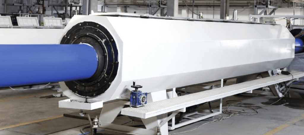
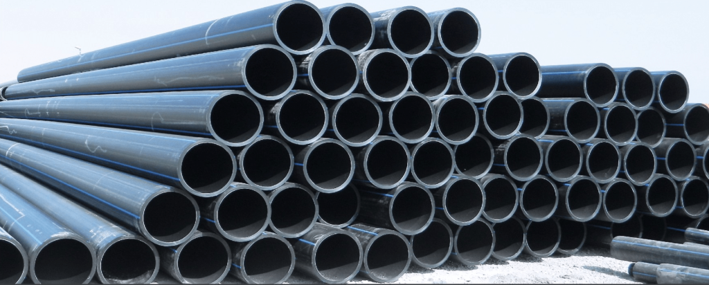
The first drinking water applications with polyethylene HDPE pipes have started to be made in the United States and Canada since the 1960s. The projects realized at that time still continue to work without any problems.
- Generation Raw Materials PE 32(LDPE) , PE 40 (LDPE)PE 63 (HDPE)
- Generation Raw Materials PE 80 (MDPE), PE 80 (HDPE)
- Generation Raw Materials PE 100 (HDPE)
ADVANTAGES
- It does not affect the smell of the water and
- Resistant to bumps, it is not affected by ground movements and impacts.
- Tensile strenght breaking point is more then %600.
- The inner surface is flat and does not cause friction loss.
- There is no waste as it is combined with the butt welding and EF technology
- It can operate 50 years under pressure .
- Resistance to sun light is strengthened by UV ad di
- They are not a ffec ted by underground plant roots and substances with chemical abrasive effect.
- Tree roots can not enter the pipe due to their joining shape and they do not cause congestion
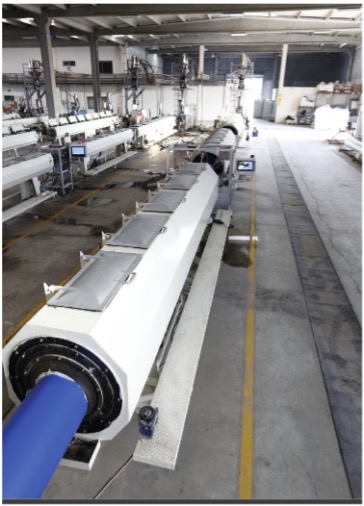

Laboratory Tests Our company conducts periodic tests in order to ensure the continuity of quality. The most important element of producing quality materials is the control of the product entering and leaving the production. For this purpose, our company has created its laboratory and has reached the level where it can perform all the tests stipulated by the standards. Our company’s quality assurance staff periodically perform the following tests. In addition, foreign organizations (such as DVGW) for which they have received their certificates, perform tests on the samples of their own choice, both in our laboratory and in their own laboratories, twice a year, and extend the certificate period by inspecting the tests we have done.
Our Tests and Purposes for Quality and Assurance MFI (Melt Flow index = Melt Flow Rate): This device is used to simulate the flow motion before the material is processed in extruders and injection machines. Information on the flow index of the device material in terms of unit temperature and time. This allows us to have information about the possible behavior of the material during the manufacturing process. The quality standard for testing is ISO 1133. Density Tester: The weight of the material passed through the MFI device is determined separately in air and in a liquid with a known density, according to the ISO 1183 standard. After these weight values are obtained, the density of the material is determined with the help of density. Impact (Izod-Charpy) Test Device: With this test, the amount of energy absorption and the possible applicable force on the unit area are determined by means of the free fall method made with materials of different weights. By doing this test, we learn about the behavior of the material under loads of different magnitudes provided by sudden impacts. Standards applied for this test: ISO 179 and ISO 180.
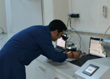

Tensile – Compression Device: With the tensile test using this device, the product’s elasticity modulus (maximum strength per unit area), maximum tension, percent elongation, deformation, expansion at the breaking point, tension at the breaking point; The ring stiffness values are also determined by the compression test. Thanks to these tests, we obtain information about the possible behavior of the material in working conditions. ISO R 527, ISO 6259 standard for tensile testing in these tests; For the compression test, the DIN EN ISO 9969 test is applied. Hallow Die Punch (Sampling Device): It is used to prepare samples for the pulling device in the dimensions specified in ISO 527. Tensile – Compression Device: It is used to cut parts for the microscope image system in order to see the internal structure of the product. Microscope Image System: The purpose of the test, which is used to see the fibrous structure of the material, is to ensure that the material has a homogeneous structure. If the structure of the fibers is not linear, it means that there is a problem at the production stage or due to the quality of the raw material.
Thermal Elongation Test: It is the test in which it is checked whether the changes in the material due to temperature differences are at the level stipulated by the standards. The standard applied for this test is EN 743. Pressure Tests: Pressure tests are applied hydrostatically according to the method in EN 921 standard. Time and temperature values are specified as 100 hours at 20°C: 165 hours at 80°C and 1000 hours at 80°C. OIT Test: With the DSC test, the homogeneity of the material, its melting temperature and crystallinity are determined. With the OIT test, the oxygen permeability time of the material is measured. Tensile – Compression Device with Heating Cabinet: Tensile – compression test was applied to the spoon-shaped sample in atmospheric environment at different temperatures from -40 to +900C. Special Tensile Device: Tensile test is applied to spoon-shaped sample in different chemicals at different temperatures under constant load.


Joining Methods with Butt Welding The method of joining with butt welding is a form of welding that is applied by bringing the pipe butt surfaces to the melting temperature in accordance with the necessary application techniques and standards, without the need for any extra joining element during the joining, and joining the pipe butts with direct contact with each other with high pressure. Devices and Equipment Used in Butt Welding Process Butt welding machine used for butt welding method consists of 4 main equipments:
Clamps: It is a fixing apparatus working with hydraulic system designed for fixing, adjusting and performing other operations on pipes and/or fittings to be butt welded. Apparatus! There are crescent adapters for working on pipes of different diameters. Trimming Unit: It is used to clean the butt surface to be welded by shaving and to make the pipes perpendicular to the axial line and to ensure that the pipe butts are in full contact with each other. Heating Unit: It is the metal plate that allows the butts to be welded to be heated and brought to the appropriate melting temperature. Hydraulic System Unit: It is the unit that provides the hydraulic pressure required for the horizontal axis movement of the clamps for all steps during the butt welding application.


Preliminary Preparations for Butt Welding Providing Necessary Weather Conditions Measurement of Air Temperature: The air temperature should be minimum + 5 °C. Humidity: By using awnings in humid weather, the humidity in the environment should be minimized or lost. Ambient temperature: The environment to be welded should be closed by technical applications such as setting up a mobile tent or using a tent in cold weather, and preheating should be done by reaching a minimum ambient temperature of +5°C with the help of heaters. Effect of Sunlight Radiation: During the application of butt welding, shade should be made in order to prevent the reaction that may occur as a result of exposure of the area to be welded to sunlight radiation. Dust Effect: Butt welding should not be done in dusty environments. Air Circulation: In order to increase the quality of the butt welding process, the pipe heads can be closed to prevent the air circulation inside the pipe.
Considerations in Butt Welding Application The pipes must be connected on the clamp in such a way that they are perpendicular to the axial line and the forehead surfaces meet each other exactly. It should be ensured that the forehead surfaces are cleaned of oxide and dirt by shaving and completely cleaned with a cleaning solution. While choosing the heat value of the iron (heater plate), a selection should be made according to the standard values table, taking into account the raw material from which the pipe is produced. After the iron reaches the set heat value, it should be waited for at least 5 more minutes. Ironing surfaces should be free of all kinds of dust, plastic residues and oxidation. During the welding process, the hydraulic unit pressure should be used in the dimensions determined in the standard table. Welding pressure test for pressure piping systems is carried out according to EN 805 standard.


Considerations in Butt Welding Application Before starting the butt welding process, the following operations should be performed after the environment to be welded is ready as stated above. Welding temperature: The welding temperature to be adjusted is related to the pipe wall thickness, the average temperature of the iron (heating plate) temperature is between 200 – 220 °C, the welding temperature value to be selected is given in the table below. Heating Pressure: The heating time is the pressure that will be fixed during the heating of the foreheads by placing the iron between the pipe forehead surfaces and the contact of the pipe forehead surfaces with the iron surface. In this process, the contact of the forehead surfaces with the iron should be kept at low pressure. During the heating process, the pressure should be fixed as P < 0.02N/mm 2. Heating Time : The time it takes for the forehead surfaces to heat up after the iron is placed between the pipe forehead surfaces and the necessary pressure is adjusted , this period : HEATING TIME = e · 10 sec. ( HEATING TIME = PIPE FALL THICKNESS X 10 SECONDS) Lip Height: It is the wall expansion that occurs on the foreheads by applying P < 0,15N/mm 2 pressure to the pipe foreheads that lean on the iron surfaces. The expanding wall height is calculated as H= 0.55mm+ (0.1e). ( LIP HEIGHT = 0.55 mm + ( 0.1 X wall thickness )
Changing Time: It is the time to remove the pipes from the iron and remove the iron from the iron in order to remove the iron, after the forehead lip height has reached the standard determined height under the specified pressure and temperature. The replacement time should not exceed the time specified in the table, otherwise the welding quality will decrease as the heated area will cool. During this period, the heated area should not be touched, polluted or impacted in any way. Joining Time: It is the time taken for the pipe surfaces to be joined to each other by pressure, right after the iron is removed from the pipes at the end of the replacement time. The time elapsed between the replacement time and the defragmentation time should be close to zero. The bonding time pressure is P = 0.15 ± 0.01 N/m m2. Cooling Time Under Pressure: The expected time for the weld to cool without changing the pressure after the butt surfaces are joined under pressure.

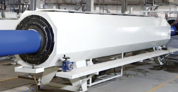
Electrofusion welding is the technique of welding the pipes and/or fittings to be joined to each other by using an EF coupling used as a joining element. In this application, it is aimed that the resistance wires in the EF coupling placed on the pipe are heated with electric current to form a bond with the pipe surfaces. remains low, this potential difference creates pressure in the welding area and performs the welding process.
MACHINERY AND EQUIPMENT REQUIRED FOR THE METHOD OF JOINING WITH ELECTROFUSION COUPLING
Electrofusion Welding Machine: It is the device that gives the necessary electric current to the cuff within the required time, together with the parameters for the welding process. Pipe Cleaning Apparatus: These are the equipment required for cleaning the surface to which the coupling will be connected by scraping from oxides and dirt. V3) Pipe Adjustment Aparts: These are auxiliary apparatus such as cutter, 90° miter used to control the verticality, and meter, which enables the pipe butts to be cut perpendicular to the horizontal axis of the pipe. Clamps: These are the side clamps that provide the elimination of the ovality of the pipes. Plastic Hammer: It is the auxiliary equipment required for the placement of the cuff.


PREPARATIONS REQUIRED FOR ELECTROFUSION WELDING
Compliance control of the electrofusion cuff (diameter control, PN value control, cuff internal and external durability eye control, etc.) Adjusting the ambient temperatures required for the welding process Dust, moisture, oil etc. from the environment to be welded. elimination of inappropriate situations such as Closing the environment in bad weather conditions such as snow, rain, wind, sunlight radiation
MATTERS TO BE CONSIDERED IN ELECTROFUSION WELDING The pipes to be welded in the electrofusion welding method must be produced from the same raw material. The MFI (melt flow rate) value of the pipes to be welded (for 190 °C /5 kg test value) should be between 0.2 – 1.3 gr/1O min. Pipes with different MFI values cannot be welded. The air temperature of the environment to be welded should be between 5 °C and 50 °C. Electrofusion welding should be done according to DVS 2207 standard.


ELECTROFUSION WELDING PARAMETER VALUES
Parameter values of the cuff to be used for welding process must be entered to electrofusion welding machines. This information to be entered is applied separately on the cuff to be used, both in the form of a barcode that the device can read thanks to the barcode reading feature of the device, and as a label on the cuff to be entered manually.
APPLICATION OF ELECTROFUSION WELDING
Cleaning is the first priority in electrofusion welding, the welding to be applied on an oxidized or dirty surface will generally be of poor quality and inappropriate according to the standards. The butts of the pipes to be welded should be perpendicular to the horizontal axis of the pipes. The pipe resistance in the middle of the sleeve to be welded is measured in meters from the outside to the inside. This size is marked on the pipe. The marked area is scraped without exaggeration with the help of tools such as scrapers, so that the pipe surface is cleaned from oxides and dirt. (pipe scraping should be between 0.1 – 0.7 mm.) After scraping, the pipe surface is cleaned with a cleaning solution. ( alcohol ) If there is ovality in the cleaned pipes, the ovality of the pipe is corrected with the help of clamps.


The sleeve to be welded on the prepared pipe is passed completely with the help of a plastic mallet. The foreheads of the pipe with the other pipe and the pipe with a coupler are abutted against each other, and the coupler is allowed to pass on the other pipe until it reaches the marked point. With the last process, it is aimed to place the sleeve symmetrically and evenly between the two pipes. After the coupler bonding process is completed, the electrofusion welding machine is connected to the sockets on the cuff. The welding process is started by entering the parametric values of the coupled cuff to the electrofusion machine. During the welding process, the pipes should not be moved or exposed to impact.
